Features
| Model | FSM-100P | FSM-100M | FSM-100P+ | FSM-100M+ |
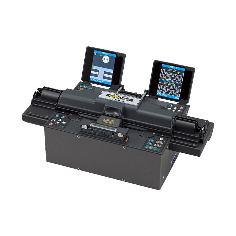
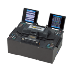
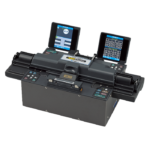
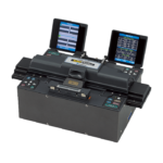
| Appearance | 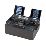 |
 |
 |
 |
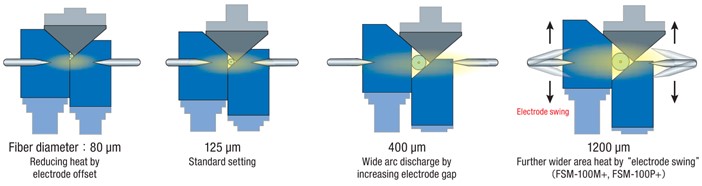
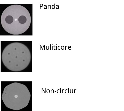
| Cladding diameter | 60 to 500μm | 60 to 1200μm | ||
| Heating area | Narrow | Wide | ||
| Electrode swing | ー | ✔ | ||
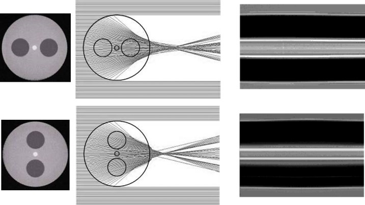
| PM Fiber splicing | ✔ | ー | ✔ | ー |
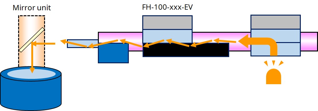
| End view fiber observation system | ー | ✔ |
||
| Sweep length | 0 to 10mm | 0 to 36mm | ||